Struggling with DOM Quality? Try 3DGS-Enhanced DOM
Anyone who has produced an orthophoto has seen the same faults. Where a wall meets the ground, the building edge rolls and smears instead of stopping cleanly. A ragged band of distortion clings to every roof perimeter. Tree canopies and shadowed facades dissolve into mush at the sheet edges.
These are usually filed under “accuracy problems”, the kind you fix with more ground control points, a tighter matching tolerance, or a newer processing engine. That diagnosis is wrong. They are not accuracy problems at all. They are the predictable output of how a conventional orthophoto is assembled, and no amount of tuning the same pipeline will remove them.
A 3DGS-Enhanced DOM takes a structurally different path to deliver. This article will explain what changes, what does not, and when the difference actually matters for your project.
Why DOM Still Matters in a 3D World
A DOM (Digital Orthophoto Map) is a georeferenced, orthorectified image of the ground, with every pixel corrected so that it represents a true top-down view at a known map position.
It is tempting to treat DOM as a legacy product from the 2D era, now superseded by meshes and digital twins. In practice the opposite has happened. As 3D deliverables proliferate, DOM has become more load-bearing, because it is the one artifact that serves as:
- The change-detection baseline. Multi-temporal comparison needs a stable, distortion-free 2D reference. Model-to-model comparison is still harder to standardize than image-to-image.
- The training ground for automated extraction. Building footprints, land cover, road networks, and object detection models are overwhelmingly trained and validated on ortho imagery.
- The common reference everyone can read. Planning approvals, cadastral cross-checks, and inter-department review all assume a flat image with a coordinate grid.
- The visual layer under vector data. Every GIS stack has an ortho underneath it.
So DOM is not going away. The question worth asking is why it keeps looking worse than the 3D model it was produced from.
How a Conventional Orthophoto Is Built
A conventional DOM is a projection problem solved by projection correction. The path looks like this:
Every arrow in that chain is a place where geometry gets approximated. And the approximations are not equally distributed. They pile up exactly where cities are hardest to map.
The Three Structural Defects
| Defect | What you actually see in the sheet | Where it is born | Why it persists in a standard DOM |
|---|---|---|---|
| Geometric distortion of vertical surfaces | Buildings lean to one side; where a vertical facade meets the ground, the wall is rolled flat and smeared across the roof edge instead of terminating cleanly | Standard orthorectification corrects terrain relief using a ground elevation model. Buildings are not terrain, so their facades are projected outward as if lying flat | A standard DOM has no model for buildings, so the facade can never be placed correctly. Nothing inside the standard pipeline removes this, which is why the industry developed true ortho |
| Perimeter occlusion artifacts | Ragged smeared bands, ghosting, or black/blurred patches cling to roof edges, eave lines, and canopy boundaries, areas the nadir camera never directly saw from above | A nadir camera never sees the ground behind a building or under a tree. Occluded area has no valid source pixel | A standard orthophoto does no visibility check, so the artifact is simply present (or hidden afterwards by a hand-drawn mask). Only a true ortho adds an explicit per-pixel test |
| Texture degradation | Soft, blocky, or seamy surfaces where flight strips were blended and resampled several times; tone jumps between adjacent strips | Multiple images averaged and blended; resampling happens more than once along the chain | Better colour balancing helps cosmetically, but resampling loss is irreversible |
The common thread: each defect originates in a modelling step standing between your images and your output.
The Defects, in Real Captures
Theory is easier to dismiss than a side-by-side. The pairs below are real outputs from the same image blocks. The conventional side is a mesh-based orthophoto, while the 3DGS-Enhanced side is a DOM rendered from a 3DGS scene. Look at the building edges and the roof perimeters.
Figure 1 — Industrial rooftop with pipework (3DGS-Enhanced TDOM vs Mesh TDOM).
| Mesh TDOM (conventional) | 3DGS-Enhanced TDOM |
|---|---|
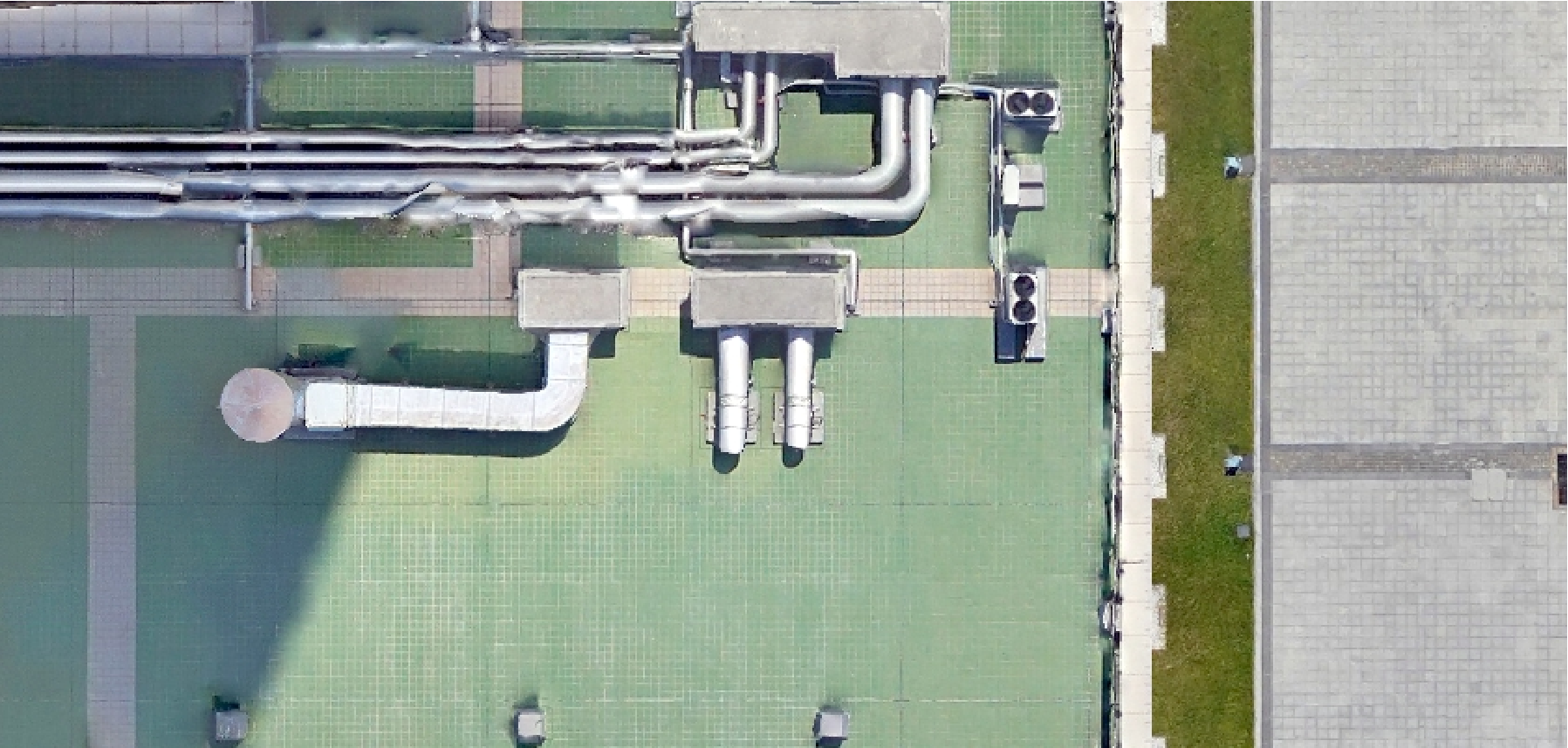 | 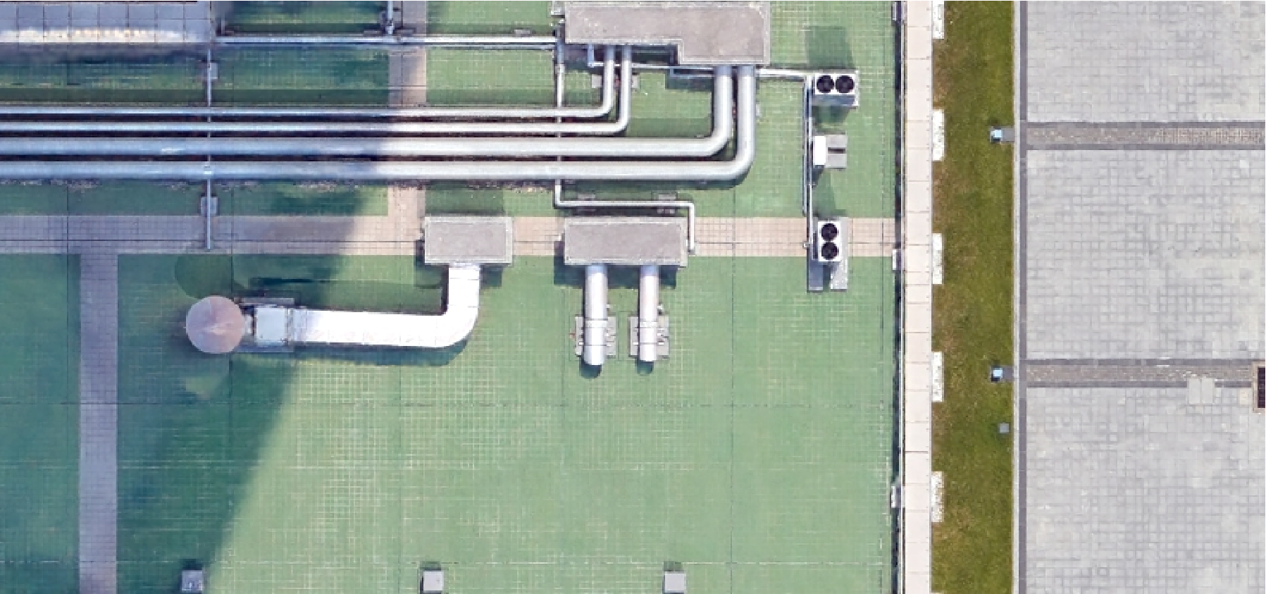 |
The mesh-based true ortho (left) renders the roof as a flat, tiled surface with geometric, projected shadows and repetitive texture. The 3DGS-Enhanced DOM (right) keeps the pipework, ducts, and shadows photorealistic and crisp. The difference is in surface fidelity, not in geometry you can measure.
Figure 2 — Dense residential block (Mesh vs 3DGS).
| DOM (conventional) | 3DGS-Enhanced DOM |
|---|---|
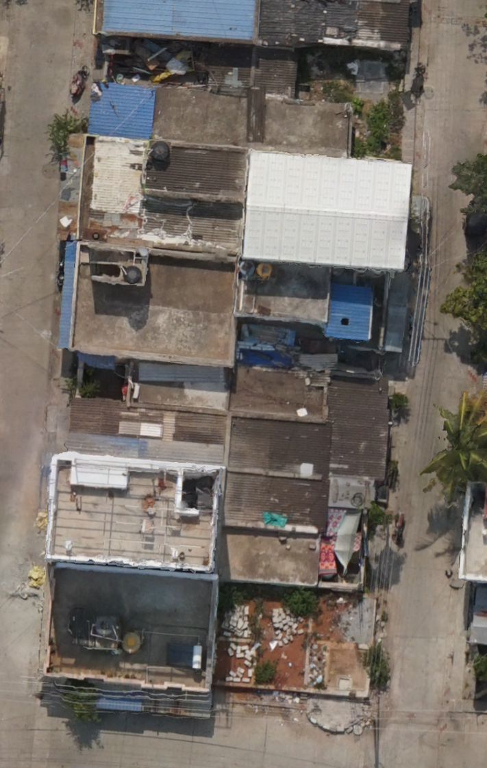 | 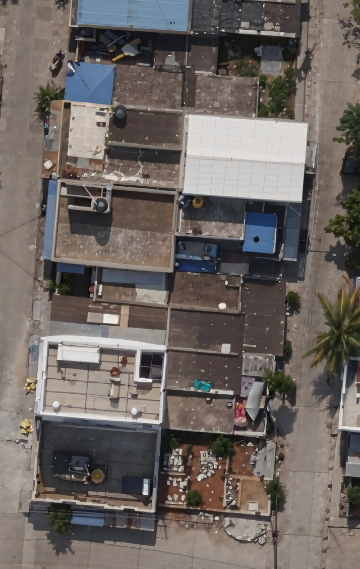 |
The conventional mesh ortho (left) shows edge distortion along the block sides, leaked side-wall geometry, and inconsistent tone between roof patches. The 3DGS-Enhanced render (right) holds straight rooflines and consistent tone across the whole strip.
Figure 3 — Four more scenes, same pattern.
| Scene | Conventional | 3DGS-Enhanced |
|---|---|---|
| Residential rooftops | 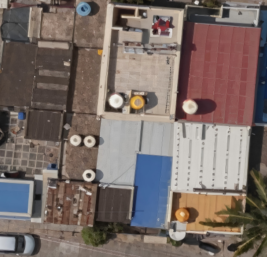 | 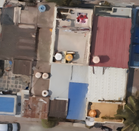 |
| Flat roof and parapet | 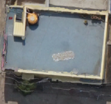 | 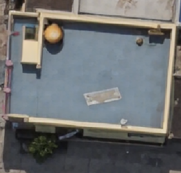 |
| Residential rooftops | 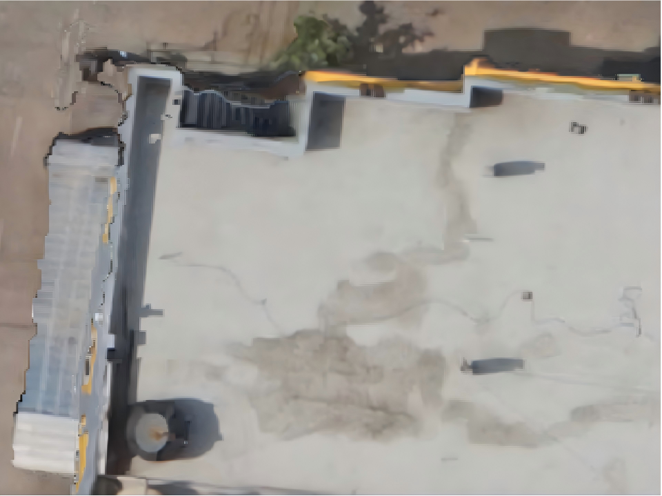 | 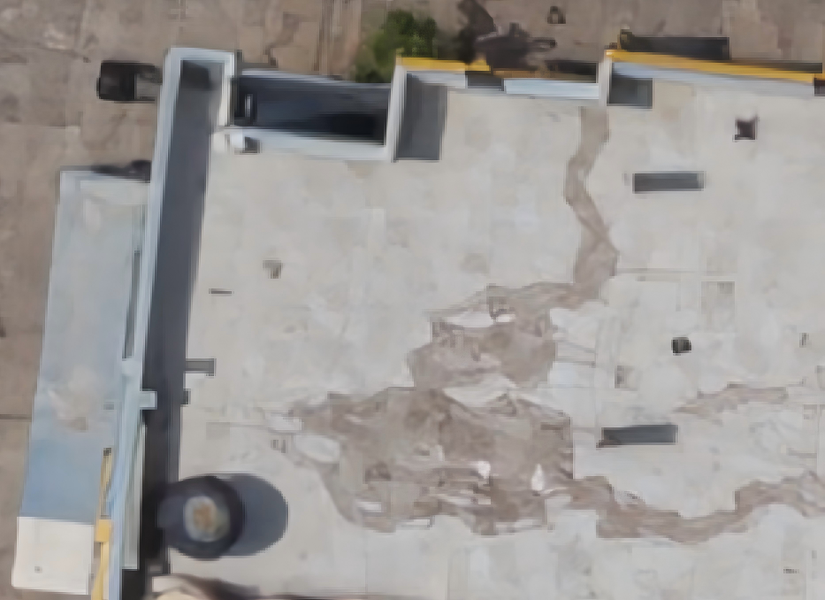 |
| Low-rise building cluster | 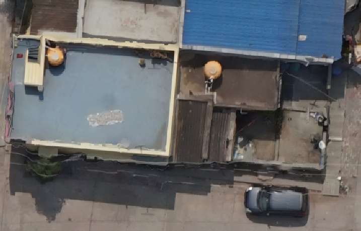 | 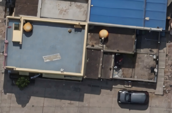 |
The same pattern holds across four more scenes. The conventional frame (left) carries smeared edges, perimeter occlusion, and tone drift; the 3DGS-Enhanced frame (right) keeps clean geometry and consistent surfaces.
True Ortho (TDOM): The Ceiling No Effort Can Break
True ortho (TDOM) is the industry’s answer to the defects above. It works by introducing a DSM into the correction, then masking out pixels that the DSM says should be hidden behind a structure.
It is a genuine improvement, and it has a hard ceiling. Three constraints hold it in place:
- The bottleneck is the DSM, not the algorithm. A true ortho cannot be geometrically better than the surface model it was corrected through. DSM edges are noisy, rooftops are approximated, and thin structures are usually lost entirely.
- Occlusion detection is a classification problem, and it fails quietly. Every pixel must be decided as visible or hidden. Under-detection leaves artifacts; over-detection punches holes.
- Hidden areas require an infill policy, and every policy is a compromise. Fill with black (honest but requires downstream handling), interpolate from neighbours (smooth but invents data), or borrow from oblique imagery (best, but needs oblique coverage and another registration step). None of these are recovered pixels. They are plausible pixels.
The deeper point: TDOM tries to reason about what the camera could not see. A rendering approach does not have to. That is what the captures above really show: not a better surface model, but a different mechanism.
A Different Path: Rendering Instead of Projecting
3D Gaussian Splatting represents a scene not as a surface, but as a dense set of 3D Gaussian primitives, each with a position, a shape (covariance), an opacity, and a view-dependent colour.
That representation changes the nature of the problem. To produce a DOM from a 3DGS scene, you do not project pixels onto a surface. You render the scene through an orthographic camera.
| Stage | DOM (standard ortho) | 3DGS-Enhanced DOM |
|---|---|---|
| Surface model required | Yes: a ground elevation model (DEM) | No |
| Occlusion handling | None: pixels are projected with no visibility check | Emergent: resolved by depth-ordered alpha compositing during rendering |
| Building edges | Not modeled: facades project flat, so edges smear and lean | Derived from the primitives themselves |
| Resampling | Multiple passes along the chain | Single render at target resolution |
| Unseen ground | Wrong, or masked by hand: no principled fill | Not applicable: the scene is rendered as a whole |
The mechanism is worth stating plainly: occlusion is not a problem that needs solving in a renderer. It is what a renderer does. Primitives are composited back-to-front from the orthographic viewpoint, so nearer surfaces naturally cover farther ones. There is no mask to get wrong, because there is no mask.
Why this needs a dedicated pipeline, not a screenshot from the 3DGS viewer
One subtlety matters technically. 3DGS appearance is view-dependent: the colour of a primitive changes with viewing angle, which is precisely what makes the rendering look convincing in perspective. But a DOM requires view consistency: the same roof must render identically across the whole sheet, regardless of where it sits relative to the camera path.
Producing a usable DOM therefore requires a dedicated orthophoto rendering pipeline that fixes the projection and normalizes appearance across the sheet. A perspective screenshot from a 3DGS viewer is not a DOM, even though it may look like one at a glance.
What Actually Improves
Four quality dimensions move in the right direction, each for a specific reason, and each is visible in the captures above:
1. Sharper building edges. Building outlines are no longer reconstructed from a surface model’s height field. Edge sharpness is set by image resolution and primitive density rather than by how the surface was sampled. Rooflines stop wobbling and stop bleeding at the perimeter (see the straight, consistent edges in Figure 2’s right frame).
2. More natural vegetation. Tree canopies are semi-transparent, multi-layered, and full of internal occlusion, the worst possible case for a hard surface model and a naturally good case for soft primitives. Canopy silhouettes keep their fine structure instead of collapsing into a solid blob.
3. Fewer occlusion artifacts. The ragged perimeter bands and ghosting seen in the conventional frames of Figures 1–2 are replaced by continuous scene rendering. There is no detection step to under- or over-trigger, so that whole class of “occlusion mistakes” largely disappears.
4. Higher visual fidelity overall. Compare the photorealistic surface in Figure 1’s right frame with the tiled, synthetic look on the left frame. Because correction happens once, at the target resolution, rather than repeatedly through resampling and blending, the finished sheet holds detail that a multi-stage mosaic usually loses.
What a 3DGS-Enhanced DOM Does Not Change
This is the part most product descriptions leave out, and it is the part that determines whether you can use the output. It is also why the comparisons above are framed as a visual-quality improvement, not a georeferencing upgrade: the 3DGS-Enhanced frame is not “more accurate” in map coordinates than the mesh frame; it is more faithful to how the surfaces actually look.
Absolute georeferencing still comes from bundle adjustment and ground control. A 3DGS-Enhanced DOM does not carry its own coordinate truth. Its position on the map is inherited from the same inputs that position any other product: camera poses, control points, and the geodetic framework. If the georeferencing is weak, the DOM will be weak in exactly the same way.
Visual fidelity is not measurability. As discussed in 03 Can You Measure from a Gaussian Splat, these are separate quality axes. A DOM that reads beautifully is not automatically a DOM you should digitize boundaries from. If your project requires survey-grade positioning, that requirement is met upstream, not by the renderer.
It does not automatically satisfy a true-ortho compliance requirement. If a specification explicitly mandates TDOM deliverables under a particular standard, the deliverable definition is a contractual matter, not a technical one. What changes is that the quality of the visual result is no longer capped by DSM quality. The acceptance criteria still have to be checked against the contract.
Some surfaces remain genuinely hard. Mirror-glass curtain walls, large open water, and uniform repetitive facades are ambiguous to any image-based method, 3DGS included. Expect improvement, not immunity.
When It Is Worth Using
High value:
- Dense urban core mapping, where perimeter distortion is most severe and most visible
- Multi-temporal change detection baselines, where edge stability directly affects false-positive rates
- AI training and validation imagery, where vegetation and edge quality affect label quality
- City-scale 3D projects that also need a DOM layer: one capture, one consistent appearance
Limited value:
- Topographic mapping over open terrain, where there is little to occlude
- Low-rise areas where edge distortion is negligible at your target GSD
- Purely internal measurement workflows where visual quality is never inspected
FAQ
Can I measure on a 3DGS-Enhanced DOM? The DOM is a raster product; its measurement reliability comes from georeferencing and resolution, the same as any orthophoto. 3DGS improves how faithfully surfaces are rendered, not how accurately the sheet is positioned. For survey-grade boundary work, validate against control as you would with any DOM.
Does it require additional ground control points? No extra requirement relative to a conventional DOM. GCPs serve the same purpose they always do: constraining the adjustment. What changes is the rendering path downstream of that adjustment.
Do I need oblique imagery? Oblique coverage improves facade and edge fidelity where present, but the occlusion handling comes from the rendering approach rather than from masking oblique data in. Nadir blocks with good overlap still benefit substantially.
Is this a replacement for true ortho? Treat it as a different way of achieving the same goal. TDOM reaches acceptable visual quality by modelling surfaces and masks; 3DGS reaches it by rendering. Both produce a flat georeferenced image. Which one fits depends on your deliverable specification and on how much DSM-driven error your project tolerates.
Will the deliverable format change? The DOM remains a georeferenced raster (typically GeoTIFF) with the same coordinate framework. The change is in how it is produced, not in what you hand over.
Does this affect processing time or file sizes? Both are workflow- and project-dependent.
Where Get3D Fits
Get3D Mapper runs a dedicated orthophoto rendering pipeline that generates DOMs from 3DGS scenes directly, without requiring a DSM and without a separate occlusion detection pass. The same image block that produces a mesh, a point cloud, or a 3DGS scene can also produce a DOM, so a single flight yields a consistent set of deliverables that all describe the same scene.
Related Articles
- 01 What is 3D Gaussian Splatting — How the underlying representation works
- 02 3DGS vs Photogrammetry — Choosing between the two for a given project
- 03 Can You Measure from a Gaussian Splat — The precision framework: visual quality vs geometric measurability
- 02 What is Oblique Photogrammetry — Why vertical imagery alone struggles in urban areas
- 02 Get3D City Modeling Solution — Full output set from a single capture
- 02 Mapper-SAT — DOM / TDOM production from satellite data